Putting a single ±0.1 mm general tolerance on an aluminum extrusion drawing rarely tells the whole story.
An extrusion can have cross-sectional dimensions such as wall thickness, slot width, and opening size, while also carrying requirements for straightness, twist, flatness, and cut length. Those are different types of variation, and they are not measured or controlled in the same way. A slot can measure correctly at several cross sections while a long profile still bows enough to create an assembly problem. A profile can also be reasonably straight while gradually twisting from one end to the other.
When we review an extrusion drawing, the more useful question is usually not “How tight can every dimension be?” It is “Which dimensions actually control fit, alignment, motion, sealing, or downstream machining?” Once those features are clear, it becomes easier to decide which dimensions can follow standard aluminum extrusion tolerances, which ones deserve a tighter requirement, and which are better finished by CNC machining after extrusion.
Aluminum Extrusion Tolerances Are Not One Universal ± Value
The Aluminum Association does not treat extrusion tolerance as one overall number. Its guidance separates dimensional and geometric conditions such as straightness, twist, flatness, and profile dimensions. The current ANSI H35.2-2024 covers dimensional tolerances for aluminum mill products, while Aluminum Standards & Data 2024 provides the corresponding aluminum product data and tolerance tables.
That structure reflects how extrusion actually behaves. The die establishes the basic cross section, but the profile still goes through cooling, stretching or straightening, aging, cutting, and sometimes secondary fabrication. Cross-sectional accuracy and the geometric condition of the full length therefore need to be considered separately.
| Tolerance item |
What it controls |
Why it matters |
| Cross-sectional dimensions |
Width, height, slot width, local spacing |
Often controls fit and assembly |
| Wall thickness |
Local section thickness |
Related to profile geometry, die design, and metal flow |
| Metal dimension |
Dimensions primarily across solid metal |
Evaluated under the applicable extrusion tolerance category |
| Space dimension |
Dimensions across openings, slots, or voids |
Influenced by the relationship between multiple walls or features |
| Straightness |
Bow along the extrusion length |
Important for rails, frames, and long assemblies |
| Twist |
Rotation of the cross section along the longitudinal axis |
Can shift mounting surfaces or features along a long part |
| Flatness |
Form of a particular surface |
Matters for mating faces and machining datums |
| Angularity |
Angular relationship between surfaces |
Affects flanges, slots, and mating geometry |
| Cut length |
Final saw-cut length |
Should be treated separately from profile and form tolerances |
This table is useful for identifying what needs to be controlled. It is not a substitute for the applicable tolerance table or a supplier-specific capability review.
Straightness, Twist, and Flatness Are Different Problems
Straightness limits bow along the length of the extrusion. Twist describes rotation of the profile around its longitudinal axis. Flatness controls the form of a surface. The Aluminum Association tolerance video series addresses them separately and provides different measurement guidance and table references for each.
For a long equipment frame, every slot width may fall within its dimensional tolerance while the full profile still bows enough to create alignment problems. Another extrusion may look straight from the side but rotate gradually along its length, changing the orientation of the mounting faces at opposite ends.
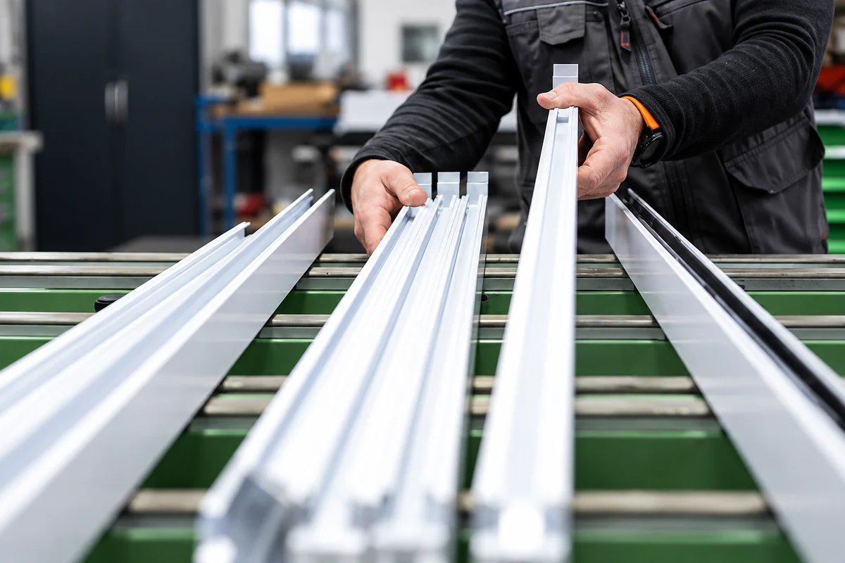
This is why an “overall ± tolerance” is not enough for long profiles. If straightness or twist matters to the assembly, the drawing should identify the actual condition being controlled and the length over which it applies. The Aluminum Association has issued separate interpretations dealing with straightness over total length versus segments and twist over a span versus segments, reinforcing that measurement length is part of the requirement.
Why Metal Dimensions and Space Dimensions Are Treated Differently
Designers who work mostly with machined parts may be less familiar with this distinction.
Under the aluminum extrusion tolerance framework, a metal dimension and a space dimension are not always evaluated the same way. In an official ANSI H35.2 interpretation, the Aluminum Association explains that a dimension is treated as a metal dimension when it is entirely across metal, or when an enclosed void occupies no more than 25% of that dimension. Larger open-space cases follow the applicable space-dimension conditions. Official interpretation
The manufacturing logic is fairly intuitive. A local solid thickness is not the same as the width of an opening formed by two separate walls. The opening depends not only on each wall but also on their relative position and on how the overall profile forms through the die.
That matters on hollow, semi-hollow, and heavily slotted profiles. A cable channel with generous clearance may not need the same tolerance attention as a slot that guides another component or provides a controlled sliding fit. The function of the dimension should decide how much control it deserves.
Standard or Precision Tolerance? Start With the Function
The Aluminum Extruders Council distinguishes between accepted industry-standard tolerances and precision tolerances. It also notes that many extruders can achieve tighter tolerances where required, but those requirements should be discussed between the designer and the extruder for the specific component.
That is more useful than marking an entire profile “precision.” If a slot controls a sliding fit or a critical locating relationship, it may justify a tighter requirement. A nearby exterior dimension that does not affect assembly may not. Tightening both simply because they appear on the same cross section can add die correction, straightening, process control, and inspection work without adding functional value.
If a critical dimension needs tighter control than the applicable standard tolerance, it is worth discussing that requirement with the extruder before tooling begins. Profile geometry, alloy, temper, size, and the way the dimension will be inspected can all affect what is practical. For projects with tighter profile requirements, see our custom aluminum extrusion capabilities.
Some Tight Features Are Better Machined After Extrusion
Mounting holes, threads, bearing seats, sealing faces, locating surfaces, and features that exist only along a short section of the final part often make more sense as secondary machining operations.
Suppose a one-meter extrusion needs a precision mounting surface only within the final 30 mm. Tightening the entire profile to accommodate that one feature may be less practical than extruding a stable section with adequate machining allowance, cutting it to length, and then machining the critical region from the final functional datum.
That approach lets extrusion produce the continuous section efficiently while CNC machining concentrates accuracy where it matters. AEC design resources treat machining, welding, bending, and other fabrication methods as part of developing an extrusion-based component.
| Design requirement |
Approach worth considering first |
Why |
| Ordinary wall thickness or noncritical profile dimensions |
Standard extrusion tolerance |
Avoid unnecessary die and process control |
| Critical slot or mating dimension |
Discuss a tighter extrusion tolerance |
Feasibility depends on profile, alloy, temper, and size |
| Full-length straightness or twist |
Specify the relevant geometric requirement separately |
A general ± value does not define it |
| Mounting holes, hole patterns, threads |
Post-extrusion machining |
Final location can be tied directly to functional datums |
| Bearing seats, sealing faces, locating surfaces |
Leave machining allowance and finish by CNC |
Keeps high precision at functional features |
| Mostly standard profile with only a few tight areas |
Extrusion + local CNC machining |
Avoids tightening the entire extrusion for a few dimensions |
This is not a fixed process-selection rule. Production volume, part length, fixturing, and machining access all affect the final route. During drawing review, asking “Does this tolerance really need to come from the extrusion process?” can prevent a local precision requirement from becoming a much broader tooling problem. Tongyong can combine extrusion with secondary CNC machining when the finished part requires drilled, tapped, milled, or precision-located features.
What Should Be Clear on the Drawing?
A useful extrusion drawing does not need to dictate every manufacturing parameter. It does need to make the functional requirements obvious.
Standard profile dimensions can reference the agreed tolerance system. Critical slots, mating openings, or locating features should be identified separately. If straightness, twist, or flatness affects assembly, those conditions should be called out rather than left for the supplier to infer from a general linear tolerance.
The standard and revision should also be clear when they form part of the acceptance criteria. The Aluminum Association currently lists ANSI H35.2-2024 and the corresponding metric edition H35.2(M)-2024 as the current dimensional-tolerance publications in this series.
Customer-specific specifications should be supplied at the RFQ stage as well. One of the easiest ways to create a first-article dispute is for the supplier to quote against an industry tolerance and then receive a different internal customer standard after tooling or sampling has already started.
In practice, we also want to know why a tight dimension is tight. Is it controlling alignment, sliding fit, sealing, appearance, or a surface that will be machined later? Once that purpose is clear, the manufacturing route is much easier to evaluate. Our engineering support page outlines the DFM and drawing-review support available before tooling.
Conclusion
Aluminum extrusion tolerances are not simply a matter of making every number smaller. Cross-sectional dimensions, wall thickness, straightness, twist, and flatness solve different problems.
A drawing becomes easier to manufacture and inspect when it separates normal extrusion requirements from the dimensions that actually control function. For most projects, the useful decision is whether each critical feature should be controlled by standard extrusion tolerances, a tighter extrusion requirement, or secondary CNC machining.
If you are developing a custom aluminum profile, send Tongyong the cross-section drawing, final cut length, alloy and temper, critical assembly dimensions, and any secondary machining requirements. We can review which tolerances are appropriate for the extrusion itself and which features may be better handled after extrusion. Send us your drawing.
References
1. The Aluminum Association — ANSI H35.2 (2024)
2. The Aluminum Association — Aluminum Standards & Data 2024
3. The Aluminum Association — Understanding Aluminum Extrusion Tolerances Video Series
4. The Aluminum Association — Standards / ANSI Interpretations
5. Aluminum Extruders Council — Aluminum Extrusion Tolerances
6. Aluminum Extruders Council — Design Resources
 Have a Custom Aluminum Project?