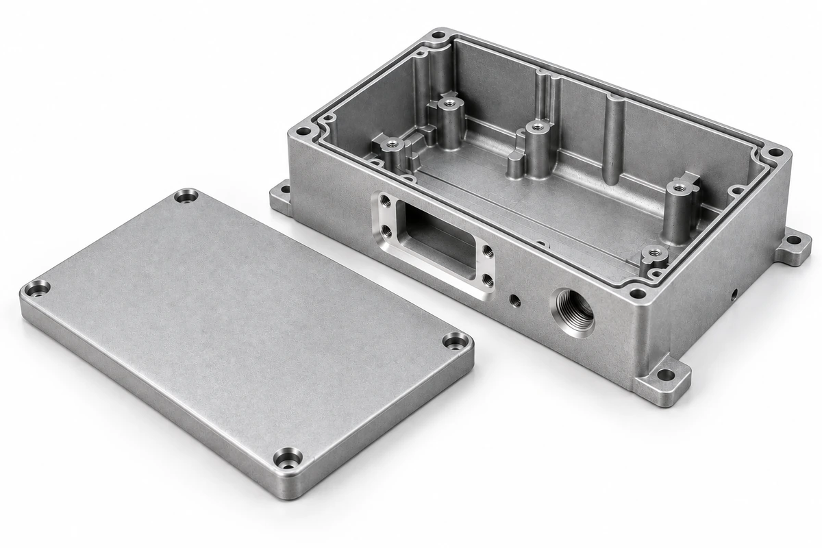
This project involved an ADC12 die-cast aluminum enclosure for industrial electronic equipment. The finished enclosure measured approximately 210 × 145 × 55 mm, with a target main-wall thickness of about 2.5 mm. After casting, several functional areas still required CNC machining, including the mounting face, locating holes, threaded holes, and selected interface features. The critical mounting face had a flatness requirement of approximately 0.10 mm.
Rather than treating casting and secondary machining as separate stages, the project was planned around the finished assembly from the beginning. We first identified which surfaces, holes, and interfaces would affect installation and fit, then used those requirements to define machining allowance, machining datums, and finishing boundaries before tooling was finalized.
This case is based on our manufacturing experience with similar die-cast aluminum enclosures. Customer identity, equipment details, and original drawings are withheld, while representative manufacturing information has been retained.
Project Overview
| Item |
Anonymized Representative Value |
| Product |
Die-cast aluminum enclosure for industrial electronics |
| Material |
ADC12 |
| Finished size |
Approx. 210 × 145 × 55 mm |
| Target main-wall thickness |
Approx. 2.5 mm |
| Main processes |
Die casting + CNC post-machining + powder coating |
| CNC-machined areas |
Mounting face, locating holes, threaded holes, interface features |
| Critical machined dimensions |
Approx. ±0.05 mm, depending on the drawing and tolerance chain |
| Mounting-face flatness |
Approx. 0.10 mm |
| Inspection focus |
Mounting face, hole locations, threads, interfaces, and finished surface condition |
Define the Machined Features Before Tooling Is Finalized
During the early review, we mapped the mounting face, locating holes, threads, and interface features back to the final assembly. From there, the die casting geometry was reviewed to determine where machining stock was required and how the part could be located consistently during secondary machining.
The enclosure body, ribs, and mounting bosses were left as cast wherever practical, while the features that directly affected fit and alignment were assigned to CNC machining. This made it possible to review machining allowance, workholding access, and datum locations while the tooling design was still being developed rather than after the castings were already available.
Plan Machining Allowance with the Casting
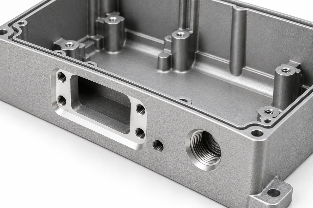
After casting, the mounting face, locating holes, threaded holes, and interface areas were machined from the predefined references. The approximately ±0.05 mm requirement applied to selected CNC-machined features rather than to the entire die-cast aluminum enclosure, while the mounting face was controlled to approximately 0.10 mm flatness for this representative project.
Machining depth also had to be considered before production. CNC machining does not create casting porosity, but it can expose subsurface porosity that was already present in the casting. For that reason, machining location, stock allowance, and the amount of material to be removed were reviewed together during the DFM review rather than treated as decisions for the machining stage alone.
Separate Functional Areas Before Powder Coating
Once machining was complete, the enclosure moved to finishing. The entire part was not treated as one uniform coating surface. Threads, selected mating areas, and interfaces sensitive to coating thickness were identified according to the drawing and either masked, kept free of coating, or reserved for local post-finishing work.
The purpose was to preserve the fit and contact conditions already established during machining. Grounding or conductive contact areas can require the same treatment in real enclosure designs.
Final Inspection Focused on the Assembly Interfaces
Final inspection concentrated on the features that would affect installation: mounting-face flatness, locating-hole positions, thread condition, interface openings, and the condition of the finished surfaces. Overall dimensions still had to meet the drawing, but assembly performance depended more directly on the relationships between these local functional features.
The ±0.05 mm machining tolerance and 0.10 mm flatness shown here are representative project requirements, not default specifications for every die-cast aluminum enclosure. Actual acceptance criteria remain defined by the drawing, datum structure, tolerance chain, and assembly requirements.
Have a Custom Aluminum Enclosure Project to Review?
If your project combines die-cast geometry with CNC-machined mounting features, interface openings, or specific finishing requirements, send the 3D model together with a 2D drawing showing the critical dimensions, tolerances, material, and surface requirements. We can review the casting geometry, machining allowance, secondary machining features, and finishing plan around the actual assembly requirements. Contact us to discuss the project.
 Have a Custom Aluminum Project?