How Aluminum Enclosures Are Made and How Geometry Guides the Process
See how bases, repeating cross sections, mounting bosses, and internal corners guide deep drawing, extrusion, and CNC machining for aluminum enclosures.
See how bases, repeating cross sections, mounting bosses, and internal corners guide deep drawing, extrusion, and CNC machining for aluminum enclosures.
Aluminum enclosures can be formed from sheet through stamping operations such as deep drawing, or machined from extruded stock or solid blanks. A part may also start with a basic shell shape, followed by CNC machining of local features. To evaluate a manufacturing route, first consider whether the base must be integral with the sidewalls, whether the cross section repeats along the length, and which areas need to retain more material.
A cylindrical metal housing for an earphone product, a digital camera's rear cover with openings around its screen and controls, and a phone frame with screw mounting points all serve as enclosures, but their structural requirements differ. These parts, together with a tablet back cover, help explain how use and assembly requirements influence the choice of deep drawing, extrusion, and CNC machining.
Consider a cylindrical earphone housing with a cap. It can be understood as a metal body, a cap, and internal components. The body creates space for the components, while its open end allows them to be inserted and connects with the cap. An opening for an interface may also be provided in the end face as needed. The first design question is whether the body's base must be integral with its sidewalls.
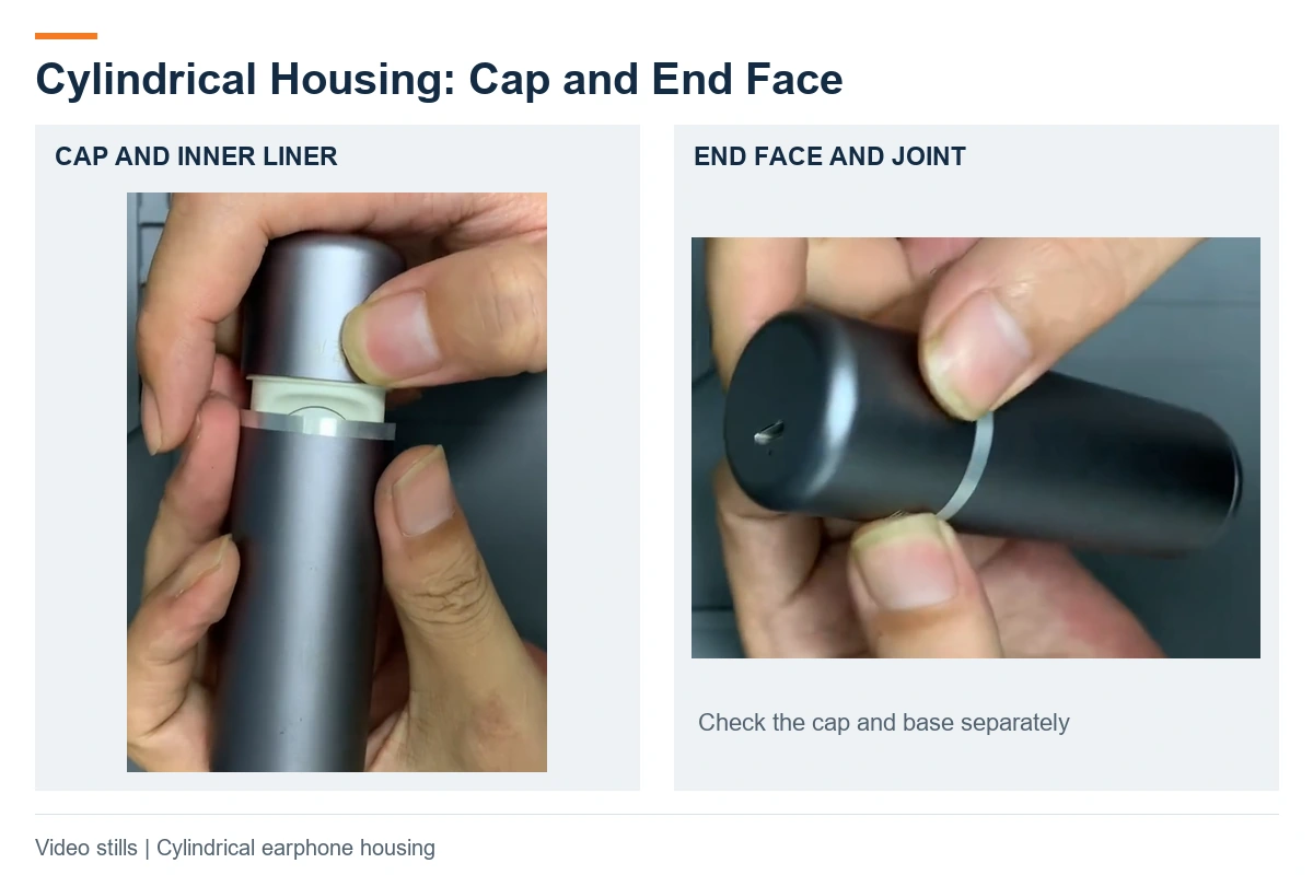
If the base and sidewalls need to come from the same sheet blank, deep drawing is a route to evaluate for a thin cup-shaped or box-shaped enclosure with one open end and an integral base at the other. Deep drawing is a sheet forming process in which a punch and die guide the blank into a die cavity to form the base and sidewalls. Where the geometry is suitable, trimming, hole making, and necessary local machining can follow the basic forming operation.
First establish which component provides the closed end. Some finished products use a sleeve that is open at both ends, together with a separate end cap. Once assembled, they also appear closed. Judging only by the assembled exterior could lead to an extruded sleeve being mistaken for a one-piece deep-drawn part. Checking for a joint around the base and distinguishing the body from the end cap in the assembly drawing is more useful than judging by surface color.
Evaluating deep drawing for a shell with an integral base requires looking at the opening size, shell depth, corner transitions, and whether the material condition is suitable for forming. Deeper shapes or more local variations may require multiple drawing operations. Unsuitable corner radii, blank holding, or material flow can lead to wrinkling, cracking, or excessive local thinning. The actual wall thickness in each area must be checked against the thickness distribution after forming.
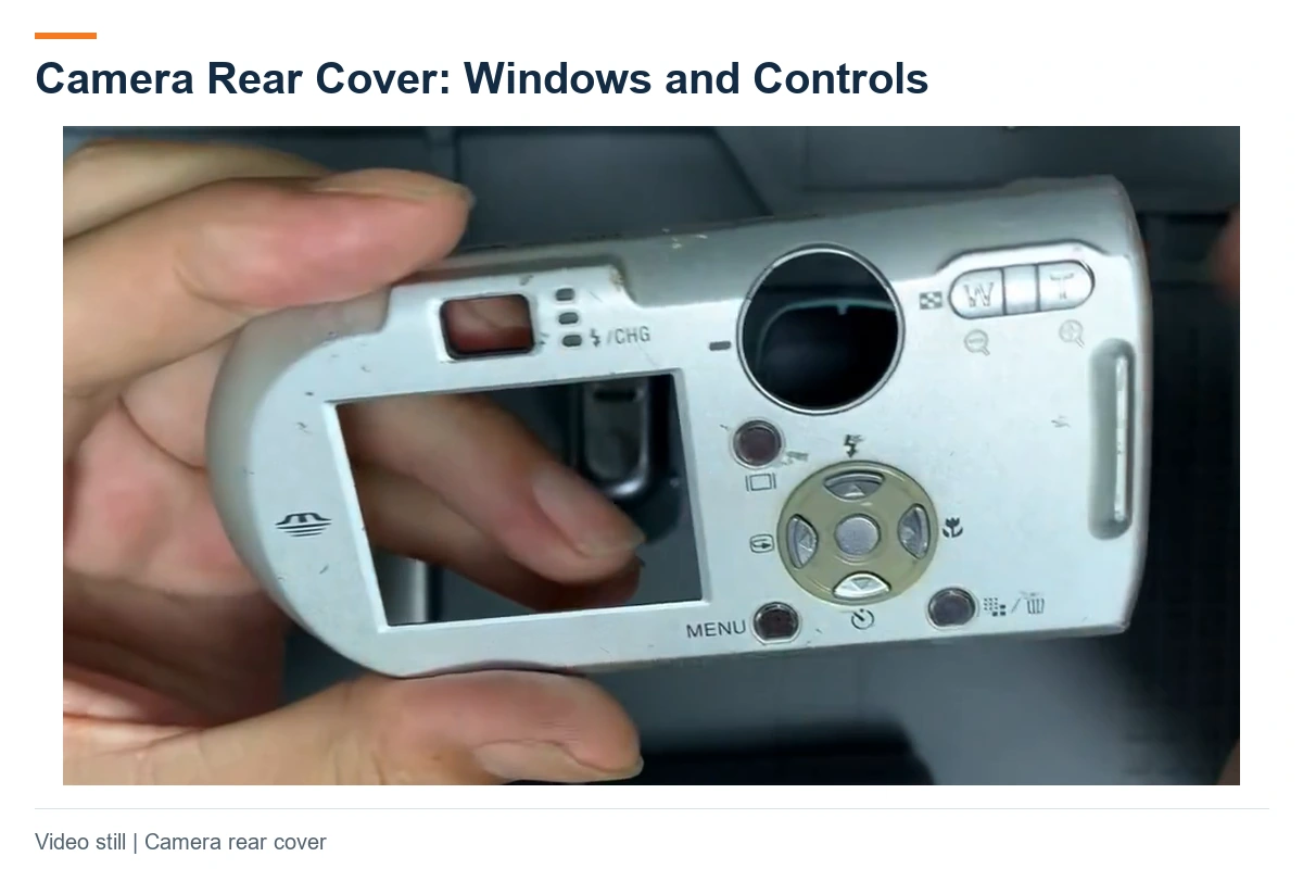
A digital camera's rear cover is closer to a shallow shell arranged around a display and operating controls. It needs space for the screen, viewfinder window, directional controls, and zoom control, while its perimeter must fit with the rest of the camera body. For this type of thin cover, first consider whether sheet forming can create the basic shape. Then plan the windows, holes, and mating surfaces separately so that their positions correspond to the internal components.
A tablet back cover is a larger shallow shell. Its interior needs room for components such as the battery and main board, and its perimeter must connect to the midframe or display assembly. When considering a sheet forming route, evaluate both the broad face and the short sidewalls, along with the secondary operations needed for edge clips, openings, and mating surfaces. Shell depth should be assessed together with the opening, cross section, and corner radii.
For a housing that is open at both ends, imagine making cuts at several positions along its length and comparing the sections. If the outer contour, internal cavity, and guide channels retain the same basic shape, conventional extrusion is worth evaluating. The die opening creates the required cross section, and the resulting profile is cut to the necessary length. For the complete production sequence, see our aluminum extrusion process guide. Here, the focus is on the relationship between the cross section and the enclosure's structure.
For example, a small electronic device could be designed so that a circuit board and internal support slide in through the end of a sleeve before the end caps are fitted. If internal channels guide or locate the board and keep the same shape along the full length, they may be extruded together with the main body. A side window that exposes a connector, or a short slot that ends partway along the body, is a local feature. Such features generally require secondary operations such as cutting, punching, or CNC machining.
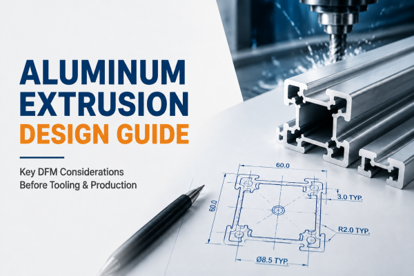
Two types of wall thickness variation need to be distinguished. A cross section may have a thicker wall in one area or include a reinforcing rib. If those features repeat continuously along the length, extrusion may still be an option. Thickness transitions affect forming, distortion, and surface quality and must be evaluated for the specific cross section. Uniform walls can help the extrusion process, but a section with different wall thicknesses can also be viable. Our aluminum extrusion design guide covers these details.
Finned heat sinks inside electronic devices provide another way to understand this principle. The fins increase the surface area available for heat transfer. If the fin and base cross section repeats along the length, they may be evaluated as a single extrusion, followed by machining of local mounting holes, ends, and surfaces that require a machined finish. A radius at a fin root may be part of the original cross section design. The actual machining plan still needs to be confirmed from the starting stock and the complete process sequence.
The internal frame of a phone makes these local features easier to understand. Components such as the main board and camera need to be positioned and secured in a confined space. The frame also connects with the display and other housing parts, so it may include screw mounting points, steps, and locally thickened areas. Each location needs to be checked for sufficient material in the blank, tool access, and a suitable method of locating and holding the part during machining.
Milling a cavity from solid plate or block while leaving bosses in place is one route to evaluate. Forming the main body first and then machining selected areas may also be suitable. For example, a thick rib that runs the full length could be included in an extruded cross section, with excess material removed locally afterward. If a boss exists at only one position, assess whether retaining stock in this way is practical before choosing between local machining and machining the whole part from solid.
When CNC machining follows stamping, check where the blank provides machining stock. Cutting only removes material. If a solid screw boss or a thicker platform must remain after machining, the blank needs enough solid material in that location. For a thin formed shell, separate mounting components or a different type of blank may also be evaluated according to the function. A combined route must account for the material and machining location required by each feature.
Local machining on a thin-walled shell also requires consideration of workholding support, distortion, and machining allowance. Dimensional requirements for holes or mating surfaces that need precision machining should be set individually according to their function. A few critical locations do not require the entire enclosure to be held to the same tight tolerances. For extruded parts, see our aluminum extrusion tolerances guide for how drawing requirements can distinguish dimensions controlled by the profile from those achieved through secondary machining.
When a conventional end mill machines a cavity through its opening, the tool's circular cutting envelope limits the concave internal corners between adjacent sidewalls. The internal radius, cavity depth, and available tools need to be considered together. A very small specified radius may require a smaller tool and additional toolpaths. It is also necessary to confirm that the tool can reach and machine the intended area reliably.
This limitation applies to specific locations. Convex corners on the outer contour, internal corners between sidewalls, and the transition where a sidewall meets the cavity floor must be assessed separately. For an external convex corner, the tool can move around the outside of the part. The shape at the wall-to-floor junction also depends on the geometry of the tool's end. Design requirements should identify each location separately.
For example, if a rectangular circuit board or electronic module must fit inside a small device housing and locate close to its inner walls, check whether its four corners will interfere with the housing's internal radii. Depending on the function, possible adjustments include chamfering the mating component, adding local relief, or changing the enclosure's internal corner geometry while retaining the necessary assembly clearance. Considering how the component is inserted and located helps identify which radii need adjustment.
Both deep drawing and extrusion may be combined with subsequent local CNC machining. On the model, first identify the main shape that the blank needs to provide, then mark the holes, slots, and functional surfaces that occur only in selected areas. Relate each location to the product's use, then use the structural clues below to narrow down the candidate routes.
| Structural clue | Route to evaluate | What to check next |
|---|---|---|
| Small thin-walled shell requiring an integral base For example, an earphone housing body |
Deep draw sheet into a shell, then trim or add openings | Material condition, depth and radii, local thinning |
| Device sleeve assembled through its ends Cross section repeats along the length |
Extrude the main body, then cut to length and machine local features | Local interface openings, end cap connections, thickness transitions |
| Housing part such as a phone frame Local bosses and mounting points |
Machine from solid or form a blank first and machine selected areas |
Sufficient stock, tool access, workholding support |
| Heat sink for an electronic device Fin and base cross section repeats along the length |
Evaluate an extruded section, then machine local mounting features | Whether the section can be extruded, local holes and slots, assembly requirements |
Even with a similar overall shape, changing an end cap connection, replacing a local boss with a continuous rib, or allowing a suitable radius in one location can change the available routes. During design, distinguish these adjustable features from the functional requirements that must remain. Then compare the candidate routes against the material condition, dimensions, appearance, and actual production quantity.
A drawing review can start with one specific question: which features can be created with the basic shell, and which need subsequent operations? Applying the answer to the ends, cross section, and internal features turns a general process name into a manufacturing plan that can be checked feature by feature.
If you are developing an aluminum enclosure, contact Tongyong with your 2D drawing or 3D model and a brief description of its application and key assembly requirements. Our professional engineering team will provide free design for manufacturability (DFM) support to help review the basic shell, local features, and practical manufacturing options.
1. NPTEL — Deep Drawing Deep drawing and redrawing principles
2. NPTEL — Design for Sheet Metal Forming Processes Material condition, radii, and blank holding
3. NPTEL — Defects in Deep Drawing Wrinkling, cracking, and local thinning
4. Aluminum Extruders Council — Extrusion Design Tips Thickness transitions and extrusion geometry
5. Aluminum Extruders Council — Machining Processes in Fabrication Secondary machining of extruded components
6. Autodesk — How to Machine Internal Corners Without Breaking Your Tools Internal corner radii and tool selection
7. IEC — IEC 60529 Degrees of Protection Provided by Enclosures IP classification scope from the public catalog
 Have a Custom Aluminum Project?
Share your drawing, 3D model, alloy and temper, critical tolerances, finish, and expected quantity. Our engineering team will review the profile and recommend a practical manufacturing approach.
FAQ
Not by itself. A CNC prototype can help check component layout, insertion paths, and interface locations. It does not reproduce the material flow in deep drawing or extrusion. If production uses one of those processes, review material condition, blank geometry, and secondary operations, then make trial parts using the planned main production process to confirm forming results, appearance, and assembly.
Not automatically. Changes in the starting stock and machining operations can change visible texture, tool marks, and the effect of subsequent finishing. Anodizing does not automatically conceal substrate defects. For a handheld product or an enclosure with visible mating seams, identify the main cosmetic surfaces and acceptable marks. Confirm samples made with the intended material, process sequence, and final finish alongside the mating housing parts under agreed viewing conditions.
No. An integral base describes the shell's structure. Protection also depends on sealing at the lid joint, display and button openings, and connectors. If dust or water protection matters, specify the operating environment and target protection requirements before selecting the manufacturing route. Validate the final configuration with its covers, seals, and interfaces assembled, using the applicable standard and test conditions. An IP rating cannot be inferred from the shell's appearance or manufacturing process.
Upload your drawings or describe your requirements. Our team will review your inquiry promptly and provide initial feedback.
We use cookies to collect information about how you use this site. We use this information to make the website work as well as possible and improve our services.more details