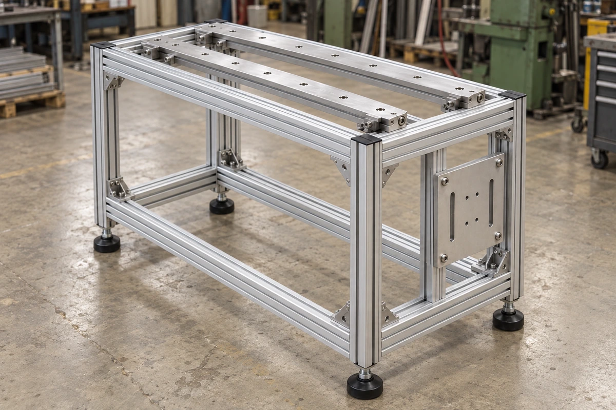
In automation equipment, an aluminum frame does more than carry the structure. It also establishes mounting relationships for guide rails, sensors, guarding, panels, and machine feet. The customer therefore needed more than stock extrusion lengths: the deliverable had to be a custom frame set cut to length, CNC-machined at key interfaces, end-processed, and supplied with the required connectors.
The frame measured approximately 900 × 650 × 750 mm and used 6063-T5 industrial aluminum profiles. The objective was not to hold every profile to the same tight tolerance; it was to keep the critical interfaces in the correct relationship after assembly. We first established the key assembly datums from the machine layout, then planned profile lengths, hole and slot machining, and connection points around those references.
Customer and equipment details are withheld for confidentiality. The dimensions below are anonymized representative values for this type of project.
Project Overview
| Item |
Anonymized Representative Value |
| Product |
Custom aluminum automation frame |
| Main material |
6063-T5 industrial aluminum profiles |
| Frame size |
Approx. 900 × 650 × 750 mm |
| Surface condition |
Pre-anodized industrial profiles |
| Main processing |
Cut-to-length, CNC holes/slots, end machining, connectors, frame assembly |
| Critical profile length |
Approx. ±0.30 mm |
| Selected mounting-hole position |
Approx. ±0.20 mm |
| Assembled diagonal difference |
Approx. ≤1.0 mm |
| Main interfaces |
Guide rails, sensors, guarding, mounting panels, machine feet |
Start with the Machine Interfaces, Not Isolated Profiles
The early review identified which locations directly controlled the guide rails, sensors, mounting panels, and guarding. Those relationships were then translated into profile lengths, machined holes and slots, and connection points. General connection features were not given the same tight tolerance as the interfaces that actually controlled machine geometry.
Profile selection was also driven by more than overall frame size. Connector access, T-nuts, end machining, and room for later changes all had to fit the section, so the final industrial aluminum profile system was selected around the machine layout and interface requirements.
Keep Cut Lengths, Machined Features, and Connections on One Assembly Scheme
This project used pre-anodized 6063-T5 profiles. The material was cut to the assembly list first, followed by CNC machining of selected mounting holes, slots, and end threads before frame assembly.
Critical profile lengths were held to approximately ±0.30 mm, while selected mounting-hole locations were controlled to approximately ±0.20 mm. Cut lengths, machined features, and connection points were tied to the same assembly references and confirmed during engineering review and machining planning.
Verify the Assembled Geometry Before Delivery
After assembly, the inspection focus shifted from individual profiles to the full frame. Guide-rail areas, sensor interfaces, guarding positions, mounting panels, and overall squareness were checked as an assembled system. For this representative 900 × 650 × 750 mm frame, the diagonal difference after assembly was controlled to approximately 1.0 mm.
The ±0.30 mm, ±0.20 mm, and ≤1.0 mm values are representative project requirements rather than default tolerances for every frame. Actual acceptance criteria depend on frame size, structural loading, guide-rail requirements, and the customer datum scheme. The relevant dimensional and assembly relationships were verified before delivery.
The final deliverable was not a collection of individually acceptable extrusion lengths, but a coordinated frame set with cut lengths, machining, and interfaces already matched to the equipment layout. This reduced on-site re-drilling and repeated interface adjustment during the customer’s equipment integration.
Need a Custom Automation Frame Built Around Your Machine Interfaces?
If your project requires more than stock extrusion lengths - for example, cut-to-length profiles, CNC-machined guide-rail or sensor interfaces, guarding connections, mounting panels, or a coordinated frame assembly - send the 3D model, equipment layout, or BOM. We can review profile size, connection strategy, interface machining, and the overall tolerance chain around the actual machine layout. Contact our team.
This representative project used 6063-T5. For higher loads, tighter stiffness targets, or other mechanical requirements, we can also review 6063-T6, other suitable alloy/temper combinations, or a custom extrusion profile.
 Have a Custom Aluminum Project?