Trial runs that come out bowed. Dies that crack a few shots in. Profiles that can’t be machined once they’re off the press. Much of this traces back to the CAD file rather than the extrusion floor, though raw material condition, tooling, and process parameters play a role too. This aluminum extrusion design guide covers the factors engineers most often need to weigh before a section goes to tooling: wall thickness, internal radii, alloy selection, and how to think about custom vs. standard profiles — with an emphasis on what’s genuinely a fixed constraint versus what needs a conversation with your extruder.
Think of this as a working set of aluminum extrusion design guidelines rather than a fixed specification. One note up front: several of the figures below are design-for-manufacturability (DFM) starting points rather than universal engineering standards. Achievable wall thickness, radii, and tolerances depend on alloy, section geometry, die design, and equipment, and final feasibility should be confirmed with your extruder before tooling.
Common Design Issues Worth Flagging Early
Before getting into specifics, here are a few issues that account for a disproportionate share of extrusion rework:
- Large differences between adjacent wall thicknesses — this can cause uneven metal flow, leaving the profile bowed or twisted.
- Sharp, unrelieved internal corners — these concentrate stress in the die and can lead to early cracking.
- Closed cavities with no tool access — these can leave a profile impossible to machine once it’s off the press.
- Alloy selection based on habit rather than load case — this can lead to strength shortfalls or inconsistent anodized finishes.
Each of these is addressable at the design stage. The sections below go into why.
Wall Thickness in Aluminum Profile Design
Wall thickness is closely tied to how far softened aluminum can flow through a die opening before flow becomes unstable. The achievable minimum wall thickness isn’t determined by alloy alone — it also depends on the profile’s circumscribing circle, whether the section is solid or hollow, die tongue ratio, extrusion ratio, die support structure, press capability, and surface or tolerance requirements. We’d avoid quoting a single minimum-wall figure as a universal design limit; thin-walled sections are worth reviewing for extrudability with your extruder before tooling.
Adjacent wall thickness balance: As a rough DFM starting point, it’s often useful to aim for a ratio of roughly 2:1 or better between clearly adjacent thick and thin regions — but this isn’t a hard limit, and whether a design can exceed it depends on alloy, section size, metal flow path, and die design. It’s a starting point for early review, not a rule to design around blindly. Significant imbalance can cause uneven metal flow, leading to bow or twist that typically requires manual straightening — a cost that adds up at volume.
Larger hollow sections: Profiles with a larger circumscribing circle generally need proportionally thicker walls to stay dimensionally stable through extrusion and cooling. The specific figure depends on section geometry and equipment capability, so it’s worth confirming with your extruder rather than assuming a fixed threshold.
Internal Corner Radii
Sharp, unrelieved internal corners are one of the more common — and more avoidable — contributors to early die failure, since stress tends to concentrate right at the corner. Extrusion design guidance generally recommends a reasonable radius transition at internal corners; the specific minimum radius should be based on nominal wall thickness, section shape, die manufacturing capability, and functional requirements, and confirmed with your extruder during die design rather than pulled from a fixed lookup table. If you’re reviewing a drawing and every internal corner is a hard 90°, that’s worth raising before the design goes to tooling.
Section Symmetry
Profiles that are balanced — top-to-bottom, left-to-right — tend to extrude more predictably. When a section is significantly asymmetric, metal flows through different parts of the die at different rates, and the resulting profile can twist beyond what’s typically acceptable, often requiring manual correction on every length. That’s a real, if often underestimated, cost at volume.
6061 vs. 6063: Alloy Selection
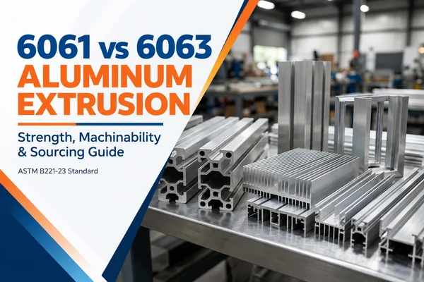
6000-series alloys dominate extrusion, but 6061 and 6063 differ meaningfully in alloying content and heat-treatment response and aren’t interchangeable by default. The table below reflects standard minimum mechanical properties (actual values vary by product form, wall thickness, and temper — confirm with your supplier’s mill certification):
| Property |
6061-T6 (standard minimum) |
6063-T5 (standard minimum, ≤12.5mm) |
Design Note |
| Tensile strength |
≥260 MPa |
≥150 MPa |
Load-bearing structures generally favor 6061 |
| Yield strength |
≥240 MPa |
≥110 MPa |
Dynamic loads and structural bases generally warrant 6061 |
| Elongation at break |
≥8–10% (varies by thickness) |
≥8% |
Ductility requirements should be evaluated against section complexity |
Alloy selection shouldn’t be based on strength alone: 6061’s higher alloying content supports greater strength, but it’s generally harder to extrude in thin, complex sections and less consistent for cosmetic anodized finishes. 6063’s lower alloying content generally means better extrudability and anodizing consistency, but noticeably lower static strength. The right choice depends on section complexity, load case, and finish requirements together.
Standard vs. Custom Tooling: How to Think About Cost
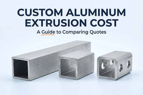
Standard catalog profiles use existing dies, carry no tooling charge, and typically ship faster — a reasonable starting point for simple frames, prototypes, and lower-volume applications, though standard sections often require extra connector hardware that adds assembly labor.
Custom tooling lets you integrate wire channels, mounting features, heat-sink fins, and locating structures into a single cross-section, reducing some downstream machining and connector needs. Whether custom tooling is worth it isn’t just a function of annual volume — it comes down to comparing:
- The one-time die investment and how it amortizes;
- Material cost per unit length and extrusion yield;
- Secondary machining costs (cutting, drilling, tapping, milling);
- Connector hardware and assembly labor saved through feature integration;
- Inventory and quality-management overhead.
These trade-offs vary by project, so it’s worth working through them with your extruder for your specific section and volume rather than relying on a fixed usage threshold.
A Design Example: The Enclosure That Couldn’t Be Machined
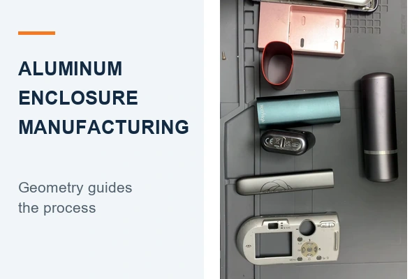
Here’s a simplified example that illustrates a common design oversight: an electronics enclosure was designed with a fully sealed internal cavity and no clearance for a cutting tool to reach the mounting datum inside. The section extruded without issue — the problem only surfaced during machining, when the CNC tool physically couldn’t get in. Reworking the cross-section and re-cutting the die pushed the project back.
The fix is straightforward to build into a design review: anywhere a tool needs to reach inside a profile, check the actual clearance against the cutter diameter, shank, tool holder, and machine interference range — not just a rule-of-thumb clearance figure — and do it before the die is finalized, not after the first batch turns out unmachinable.
Documentation Checklist for a Feasibility Review
Incomplete drawings are one of the most common reasons projects go back and forth before tooling starts. Before submitting a section for feasibility review, it’s worth having ready:
- Full operating conditions and load requirements
- A 2D CAD drawing or STEP/IGS 3D model with wall thicknesses and radii fully dimensioned
- Total length and tolerance requirements
- Target alloy and temper (e.g., 6061-T6 or 6063-T5)
- Surface finish requirements (mill finish, anodize type, powder coat, etc.)
- Estimated order volume and annual usage, to evaluate tooling cost amortization
- All secondary operations: cutting, drilling, tapping, milling, weld points
- Material and compliance requirements — RoHS/REACH declarations or mill test certificates (MTCs), as applicable
- Supplier quality-system requirements — ISO 9001 certification, if required
With complete documentation, most extruders can turn around an initial round of feasibility feedback fairly quickly; more complex sections may need additional time for tooling and process review — worth confirming directly with your supplier.
Further Reading and Standards
North American aluminum extrusion projects typically determine dimensional tolerances using the applicable product specification together with the tolerance tables in ANSI H35.2 (Aluminum Standards and Data, published by The Aluminum Association). ASTM B221 primarily governs alloy, temper, and mechanical property requirements for extruded bar, rod, wire, profile, and tube products rather than dimensional design tables. The Aluminum Association and the Aluminum Extruders Council (AEC) both publish extrusion design-related technical resources worth keeping on hand — final design feasibility for a specific section should be confirmed with your extruder.
Get a Feasibility Review
If you’ve got a section in development, our engineering team can provide an initial extrudability assessment and help flag wall-thickness and radius considerations before tooling starts. Upload your drawing through our Engineering Support Page, and we’ll follow up with a timeline based on section complexity.
Once the die is cut, the next question is usually “what actually happens on the press?” — that’s covered in our companion piece, Aluminum Extrusion Process Explained: From Billet to Finished Profile.
 Have a Custom Aluminum Project?